About Us

BUY NOW

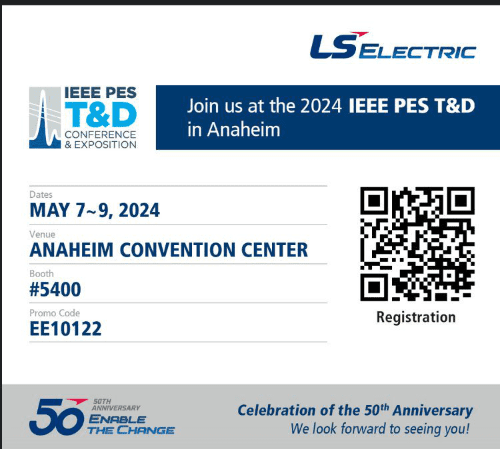
EVENTS

CONTACT US

LS ELECTRIC
Business Solutions
Panel Control
Automation
Power Distribution
featured products
G100
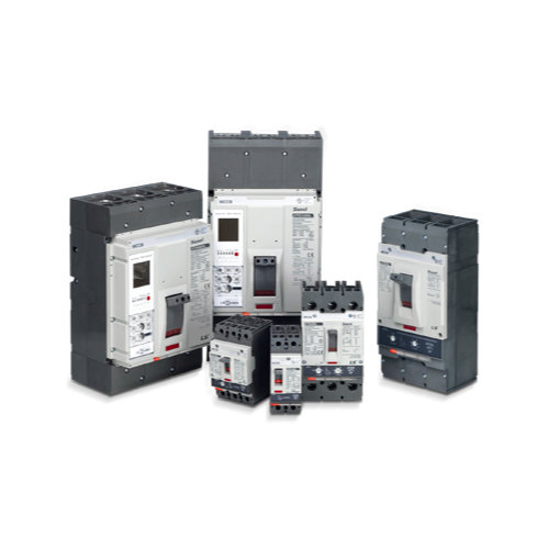
MCCB
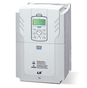
H100 Plus
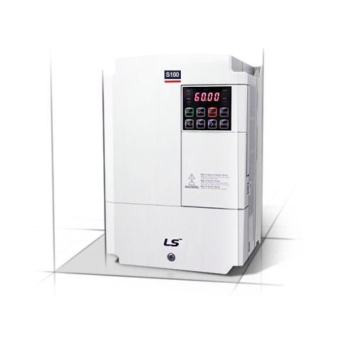
S100
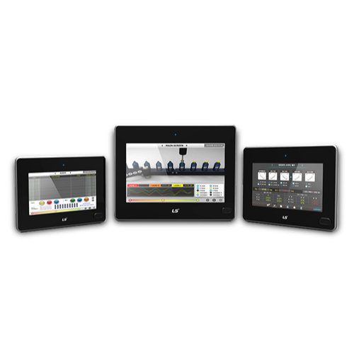
eXP Series
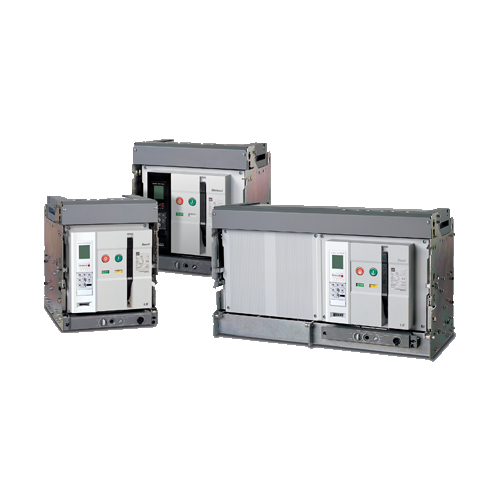
ACB

Location
625 Heathrow Dr.
Lincolnshire, IL. 60069, USA
Sales: (800) 891-2941
sales.us@lselectricamerica.com
Tech Support: (800) 891-2941
![]()
![]()
![]()
![]()
Copyright © 2021 LS Electric America. All Rights Reserved.