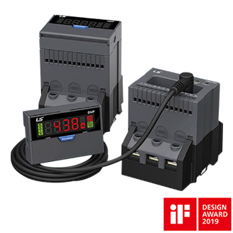
DMPi
Intelligent Digital Motor Protection Relay
• Definite/Inverse time option and various protection methods
• Storage of causes of failure
• Separated display part using cables
• MODBUS communication, 4~20mA DC output
• Operating time displayed for each model

Features
Specification
Download
Features
Convenience
- Integrated Digital Motor Protection Relay based on MCU(Microprocessor Control Unit)
- Applicable to invertor circuits
- A function to store the cause(s) of failure/fault exists
- Up to five motor failure events may be saved in the system so that failure history may be easily identified
- Communication function
- A wide range of reset functions
- Date information display
- Password setting
- Total operating time and operating time setting
- Terminal/Penetrated types are shared for application in various installation environments
Reliability
- Thermal inverse time, inverse time, and definite time modes
- Three-phase digital ampere-meter
- Various protection elements and additional functions
- High reliability
- Inverse time characteristic for motor protection
Specification
| Rating | Specification |
|---|---|
| Communication code | 1 ~ 247 |
| Communication speed | 9600, 19200, 38400, 57600 bps |
| Communication parity | None, Even, Odd |
| Fixed to 1bit | 1bit |
| Communication data swap | Limited to float, long data of Off / On (0x04 (Read input registers)) |
| Rating | Specification | |
|---|---|---|
| Protection funtions | Overcurrent, phase fail, phase unbalance, stall, locked rotor, reverse phase, ground fault (Type option)Instance (Type option) |
|
| Connection method | Penetrated / Terminaltype | |
| Operating time characteristics | Thermal heat build-up inverse time / Non-thermal heat build-up inverse time / Definite time | |
| Rated current | 0.5~6A/5~65A(Rating option upon placing an order) | |
| Display | 4 digit, 7-Segment | |
| Operating power | AC/DC 85~260V(50Hz/60Hz) | |
| Reset method | Automatic | 1~20min (only for overcurrent) |
| Manual | (Electrical reset) | |
| Installation / Mounting method | Display can be installed separately, 35mm DIN rail / Screw installation | |
| Tolerance | Current | ±3% |
| Time | ±5% | |
| 4~20mA output | ±5% | |
| Time setting | Startup delay | 1~200sec |
| Operation delay | 1~60sec | |
| Aux. contact | Composition | 3-SPST(Power supply 1a1b, i nstantaneous operation 1a) |
| Capacity | 3A/250VAC Resistive Load | |
| Contact minimum load | 100mA / 6VDC : (95-996, 97-98) | |
| 10mA / 5VDC ( 07-08) | ||
| ZCT Input | External | 200mA/100mV(Exclusive ZCT) |
| Built-in | Support (Separate connection unnecessary | |
| Service environment | Service temperature | -20℃ ~ 60℃ |
| Storage temperature | -30℃ ~ 70℃ | |
| Relative humidity | Below 50% RH (Without condensation) | |
| Insulation resistance | 100MΩ/500VDC | |
| Lightning impulse voltage | 1.2X50us 5kV Prototype waveform supply | |
| Fast transient | 2kV/1Min | |
| Power consumption | Below 2W | |
Downloads

Location
625 Heathrow Dr.
Lincolnshire, IL. 60069, USA
Sales: (800) 891-2941
sales.us@lselectricamerica.com
Tech Support: (800) 891-2941
Copyright © 2021 LS Electric America. All Rights Reserved. | Privacy Policy


